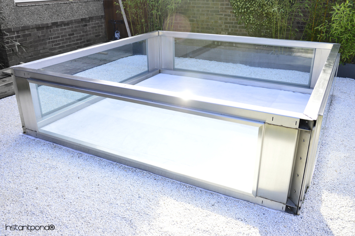
The instant koi pond - Assembly Instructions:
Overview Instructions:
1. Level base (lawn, concrete, patio).
2. Align pond walls - Bolt together.
4. Seal in the box-welded pond liner.
3. Slide on side finishing components.
5. Slide on top finishing components.
6. Top up!
Fully Detailed Instructions:
Each pond is sent out with full instructions. Please read all the instructions carefully before commencing. If you have any questions please contact us on 01255814101. (Assembly video in progress).
1. General preparation for the pond area:
If your intended site has firm soil then you will just need to level the area for the frame and the liner. If you have unstable crumbly soil you may need to put a firmer base down. If you are going to put the pond onto bricks or slabs so that you can cut the grass around the pond, you will need to level them so the frame has a flat surface to sit on. If you are having a deeper below ground box liner make sure when you lay your bricks/slabs they do not go inside the frame as this will give an uneven area for the box liner walls. Alternatively you can cut a small trench, with the inner edge in line with the inside of the frame. this needs to be about 4" deep and about 10" wide to go all around the perimeter of the pond and fill with an 8 - 1 sand/ballast cement mix and level.
2. Alignment (Fixing of the pond walls and locking):
• You are now ready to place the first section of pond wall into position. This will need steadying until you have bolted the next section to it. The second section should be placed against the first, with the corners touching and pond walls at 90 degrees to each other Fig. 1.
• The frames have two 10 mm diameter location holes at each end Fig. 2. Use the supplied tapered rods in the the 10 mm holes to align the frames, see Fig.2, so that the clamping bolts can be fitted. The six bolts and washers for each corner joint have collars of the correct length so when the nuts and bolts are fully tightened the neoprene seal will be compressed between the corner joint. The bolts, with washers and collars, should be placed into the holes through both frames so that the washer under the bolt heads fit flat against one frame and the collar on the bolt can be seen through the hole in the other frame, see Fig.3. Place a washer and nut onto the thread. The nuts and bolts should be hand tightened only at this stage to allow for any adjustment if needed when you later check diagonals, so that your pond will be square and the seals will be flat against the flanges.


Figs. 1-3: Align the 316 stainless steel frames.
• The measurement across the diagonals of the pond (without top finishing components) is 5376 mm. Once you have the right measurement you can repeat the process for the next side. Make sure that side 1 and 3 are parallel, if not, only move side 3 as 1 and 2 are now set. Side 4 can be put in position and held while the location pins are put in the two holes of corner joint three, lightly screw the 6 bolts, nuts and washers together. Check both diagonals are the same, if any adjustment is needed ease the longer diagonal in to make them the same. You can now tighten all the bolts in turn one turn at a time, checking diagonals as you go until the nut and bolts are tight, the washers will tighten down on the bolt collars, so no need to over tighten (19Nm (37ft lb)).
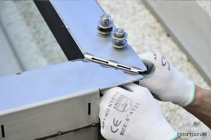
Fig. 4: Hand tighten stainless steel bolts.
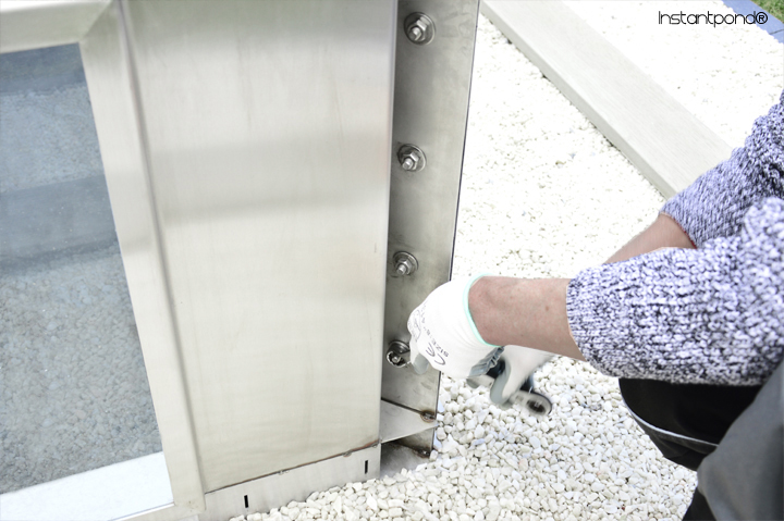
Fig. 5: Fully tighten stainless steel bolts to 19Nm (37ft lb).
3. Sealing of the corner joints:
• It is easier to put the underlay and liner in position before you seal the corner joints. Place the underlay in position, it should fit snugly into the bottom corner of the side frames remove any excess with scissors.
• On the ponds that are having a liner positioned level with the surface, layout the liner with the lip facing upwards,
With deeper box liners the tags will be the right spacing down from the top edge. Push the liner corner tags through the gap at the bottom of each corner under the black neoprene gasket, once through, gently pull into position from the outside. These tags once fitted into the securing slot should be turned at 90 degrees to lock into position, as shown in the video and fig 715. The securing slot is on the outside under the bottom frame clamping bolt, on the right hand clamping flange.
• The side frame joints will have been pre taped down each corner, you will notice the back neoprene gasket set back sightly in the corners, this is to allow for a good bead of polymer to fill the corner. Place a piece of wood on the corner of the liner to keep it down out of the way when you apply the polymer to the corner joints.
• You should apply enough polymer so that once smoothed out, the polymer will reach the tape on either side of the joint. We use the end of a polymer cartridge for smoothing out, once a smooth seal has been formed all the way up you can remove the tape and clean the cartridge of polymer ready for smoothing out the next corner. If the polymer starts to drag use clean water in a sprayer to mist it over and try again with a cleaned cartridge.

Fig. 6: Sealed corner joint.
4. Sealing of the pond liner:
• The liner is in position being held with the tags, remove the wood that you placed in the corners to hold the liner
down as you go around the bottom beam. Check that the surface of the liner and the beam are clean all the way round.
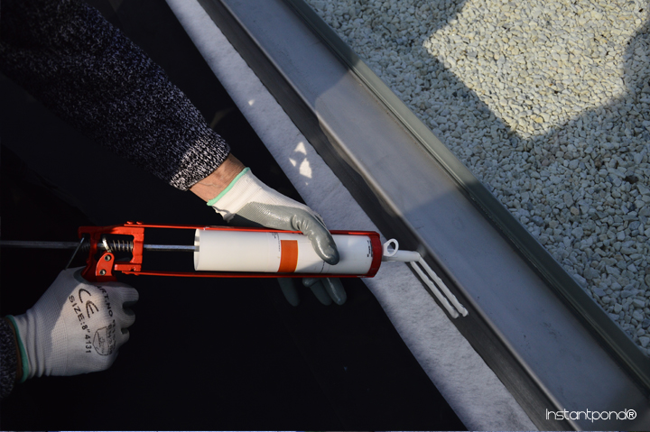
• Apply an 8 mm bead of polymer in the position shown on the video, about 25 mm down from the top of the beam. Start where shown just before a corner , so that when you have gone all the way around you can just pull the liner away slightly and go over the first flattened bead of polymer with another application to make sure there is a continuous seal. We use a wallpaper seam roller to gently flatten the polymer as you go, if you roll it out to 1 - 2 mm thick it will give a wide bonding surface between the liner and the frame, care should be taken not to stretch the liner as you may then end up with excess liner when you reach the next corner.
 -----
----- 
Figs. 7-9: Sealing the box-welded pond liner.
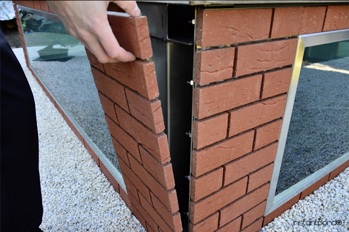
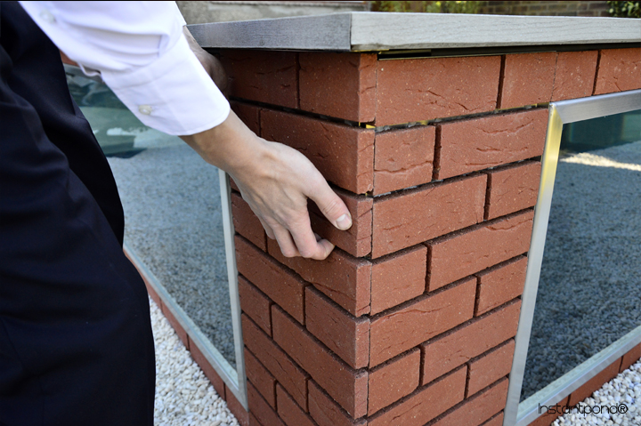
5. Attaching the side finishing components:
• The brick slip carriers can be fitted next, it is just a matter of lifting them into place. The carriers are handed and they may even have A, B, C, D, or as many letters for each corner or extension joint your particular design has they are marked left hand and right hand looking from outside the pond. Just lift them, placing the lugs on the back of the carriers into the slots on the bottom beams first then keeping the bottom edge against the pond, gently place the top of the carrier against the pond, if you then lift you will feel the carrier plate go into the slots. The plates can then be lowered into there finished locations. When fitted correctly the front surface of the bricks will be level with the window frame and the bricks over and under the window will be level with the bricks on the carriers.
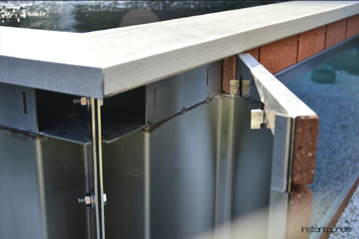
Fig 10: Brick slip carriers lugs and frame securing slots.
 ----
----  ---
--- 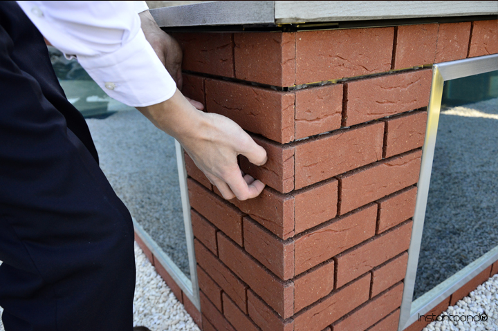
Fig 11: Slide brick slip carriers into securing slots; Figs 12-13: lower into finished location.
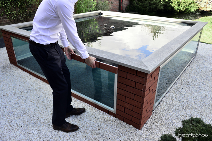
Fig 14: If applicable - Slide middle brick slip carriers into securing slots.
6. Attaching the top finishing components:
• One of the coping securing plates that is on the left hand end of the coping has a slot, this is to correspond with a cutout in the right hand end of one of the copings and should be positioned on the corner that would be used to enable pump cables or air stone tubes to enter the pond unnoticed and be adjacent to an electrical supply. The electric cables should be fitted by a qualified electrician and be to the regulations for your area.
• The coping is the last thing to be fitted. You will notice there is a round headed screw in the middle on the underside of the board, this goes in the keyhole slot in the middle top beam. There will be an attachment plate secured to the underside of the left hand end of each coping. The 4 holes are pre-drilled in the adjoining board, do not over tighten the screws. The boards are fixed in this way to allow for the expansion and contraction rates of the different materials.
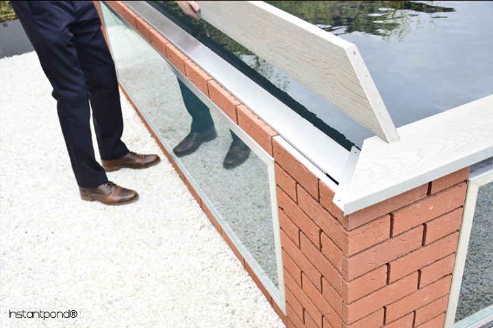
Fig 15: Slide top finishing components onto frames.
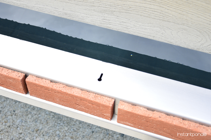
Fig 16: Slide top finishing components into the keyhole slots.
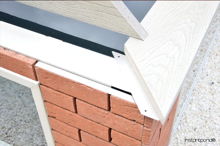
Fig 17: Attach the top finishing component corner joints.
To dismantle the instant pond please view the following instructions video:
Please contact us if you need any more information on 01255814101 or contact@atlanticagardens.com.
No comments:
Post a Comment